- New
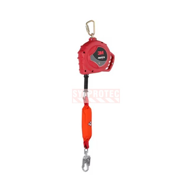
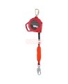
The PROTECTA Rebel 3590544 self-retracting lifeline is certified to CSA Z259.2.2-17 for leading edges (SRD-LE). Its corrosion resistant 7/32 in (5.56 mm) galvanized steel wire rope is 33 ft (10 m) long and provides a 30.1 ft (9.2 m) working length. The external polyester energy absorber with fall indicator limits forces when the cable is loaded over an edge. Red thermoplastic housing, carrying handle, swivel eye and anchorage carabiner included. Capacity of 130 to 310 lb (59 to 140 kg), including clothing and tools.
This item is not stocked. Allow 12 days for delivery.
No returnable if used. For more information about our return policy, please refer to the Orders and Returns.
3M Protecta manufacturer code: 7012819420, model 3590544
The PROTECTA Rebel 3590544 self-retracting lifeline is an SRL built for leading edge work and certified to CSA Z259.2.2-17 in the SRD-LE class. It is designed for workers who tie off at the level of the working surface, near a slab edge, steel decking or a roof, where the cable may rest on an edge during a fall. Its 7/32 in (5.56 mm) galvanized steel wire rope is 33 ft (10 m) long overall and provides a working length of 30.1 ft (9.2 m). An external polyester energy absorber, located at the end of the cable just before the snap hook, absorbs the shock when the line is loaded over an edge and limits the forces transmitted to the worker.
The device comes ready to connect. A steel anchorage carabiner (model 2000112, 11/16 in or 17 mm gate opening) attaches to the anchorage point through the swivel eye of the housing, and a steel swivel self-locking snap hook (model 2000175, 3/4 in or 19 mm gate opening) connects to the harness. Each connector has a gate strength of 3,600 lbf (16 kN) and a tensile strength of 5,000 lbf (22.2 kN). The CSA capacity is 130 to 310 lb (59 to 140 kg) for one user, including clothing, tools and equipment.
This item is not stocked. Allow 12 days for delivery.
This SRL-LE combines a galvanized steel cable, an external absorber designed for falls over an edge and a lightweight thermoplastic housing. The cable follows the worker without excess slack, retracts as the worker moves back toward the anchorage and locks through a speed-sensing brake system as soon as a fall begins. Constant tension on the line reduces snagging and tripping hazards on the job site, and the built-in handle makes it easy to carry the device to the anchorage point.
The galvanized steel cable is at the heart of this lifeline. As 3M points out, leading edge lifelines combine a sturdy steel cable and an energy absorber to better protect the line when it contacts a sharp edge. The zinc coating of the cable gives it good corrosion resistance against the moisture and weather of outdoor job sites, and 3M lists corrosion resistant components on this model. The thermoplastic housing is lightweight, compact and durable; it protects the aluminum drum and the internal mechanism made of stainless steel, steel and aluminum. The polyester absorber, sheathed in a cover of the same fabric, dissipates fall energy and can be checked at a glance during inspection. The connectors and swivel eye are made of steel. The device weighs 18.96 lb (8.6 kg).
| Manufacturer model | 3590544, Rebel series, Protecta |
| Classification | CSA Z259.2.2-17, SRD-LE (leading edge) |
| Overall cable length | 33 ft (10 m) |
| Working length | 30.1 ft (9.2 m) |
| Cable | Galvanized steel, 7/32 in (5.56 mm) |
| Housing | Red thermoplastic, steel swivel eye, built-in handle |
| Energy absorber | External, polyester cover and webbing |
| Anchorage connector | Steel carabiner 2000112, 11/16 in (17 mm) gate opening |
| Harness connector | Steel swivel self-locking snap hook 2000175, 3/4 in (19 mm) gate opening |
| Connector strength | Gate 3,600 lbf (16 kN), tensile 5,000 lbf (22.2 kN) |
| CSA capacity | 130 to 310 lb (59 to 140 kg), including clothing and tools, 1 user |
| CSA arresting force | Maximum 1,800 lbf (8 kN), average 1,350 lbf (6 kN) |
| Maximum free fall at the edge | 5 ft (1.5 m), from the dorsal D-ring to the working surface |
| Minimum clearance | Vertical 6 ft (1.8 m), leading edge 16.5 ft (5.03 m), then per the SRD-LE chart |
| Dimensions (length X width X depth) | 42 X 11.1 X 4.6 in (106.7 X 28.3 X 11.7 cm), connectors and absorber included |
| Weight | 18.96 lb (8.6 kg) |
| Country of origin | United States |
With a leading edge device, clearance depends on the geometry of the workstation. The minimum installation setback is 24 in (0.61 m), measured from the anchorage connection point to the edge of the working surface; this does not replace the required clearance calculation using the manufacturer’s SRD-LE chart. The anchorage must support 5,000 lbf (22.2 kN) if it is not certified, or two times the maximum arresting force if it is certified. Install it at the same height as the edge where a fall could occur, or higher: an anchorage below the edge would make the cable pass over the edge at less than 90 degrees. The cable must cross the edge at an angle of at least 90 degrees. Never work on the far side of an opening, opposite the anchorage, and never use a D-ring extension with this device at the edge. Work as directly in line with the anchorage point as possible to reduce swing.
The minimum values published for this model are 6 ft (1.8 m) of vertical clearance, only when the device is mounted directly above the user, and 16.5 ft (5.03 m) for leading edge use. This 16.5 ft figure is a starting point: the required clearance increases with the setback distance between the anchorage and the edge, with the horizontal distance travelled along the edge and with swing. The manufacturer's SRD-LE chart is read with these two distances, always rounding up to the next listed value. The maximum free fall is 5 ft (1.5 m), measured from the dorsal D-ring to the working surface, and 2 ft (0.6 m) when the device is mounted above the dorsal D-ring. Under the CSA Z259.2.2-17 calculation, the D140 deployment factor is 1.1; maximum deployment reaches 1.1 m (43 in) with an overhead anchorage and 2.75 m (9 ft) when free fall is possible. These values assume a rigid, stationary anchorage: with a horizontal lifeline, follow the charts from the manufacturer of that system.
The illustrations below show the principle of fall clearance for a self-retracting lifeline. For this model, follow the clearance chart specific to SRD-LE devices in the Rebel IFU attached to this page, established for a user of 130 to 310 lb (59 to 140 kg). Also have a written rescue plan in place before work begins: leading edge use may require special rescue procedures.


The worker inspects the lifeline before each use. The worker checks that the housing is not cracked or distorted, that the swivel eye pivots freely, that the cable pulls out and retracts fully without hesitation and that the device locks firmly when the cable is jerked sharply. The cable is examined along its full length for cuts, kinks, broken wires, bird-caging, welding spatter, corrosion or severely abraded areas. The cable assembly must be replaced if there are six or more broken wires in one lay, three or more broken wires in one strand in one lay, or any broken wire within 1 in (25 mm) of the ferrules. The worker also checks that both connectors open, close and lock properly, then confirms that the absorber has not been activated: the cover must be intact and no inner webbing should be visible.
A competent person other than the user must also inspect the device at least once a year, more often under heavy use or harsh conditions, and each inspection is recorded in the IFU log. Any lifeline that has arrested a fall or been subjected to impact must be removed from service immediately and tagged "DO NOT USE". It may return to service only with the written approval of a competent person, and only 3M or an authorized service center may repair it. Sylprotec offers a fall protection inspection service; to learn more, see the Services tab.
Periodically clean the cable and the outside of the housing with warm water and a mild soap solution, rinse thoroughly and let air dry. Clean the labels as needed: they must remain legible. Do not disassemble the device or lubricate any parts. Store and transport the lifeline in a cool, dry, clean place out of direct sunlight and away from chemical vapors, and inspect it thoroughly after extended storage.
When the lifeline will be left unused for more than 24 hours, 3M recommends fully retracting the cable into the housing to spare the retraction spring. A tagline, a light cord 3/16 in to 1/2 in in diameter made of polypropylene or nylon, attached to the snap hook and long enough to retrieve it from a safe location, allows this controlled retraction. Never let the cable retract freely at high speed, and never use the tagline for fall arrest or restraint. The service life depends on working conditions and maintenance: the lifeline remains in service as long as it meets the inspection criteria.
It is a self-retracting lifeline of the SRD-LE class, designed for use where the cable stays generally horizontal and may rest on an edge while a fall is arrested. This model has been tested for horizontal use and for falls over a steel edge without burrs; its external absorber then limits the forces on the user. Standard self-retracting lifelines must not be used in these situations.
Under CSA Z259.2.2-17, it is suitable for one user of 130 to 310 lb (59 to 140 kg), including clothing, tools and equipment. The capacity of the complete system remains limited by its lowest rated component.
The cable is 33 ft (10 m) long overall. The working length, which is the distance actually available for moving around, is 30.1 ft (9.2 m) according to the current IFU. Plan the work area using the working length.
A steel anchorage carabiner (11/16 in or 17 mm gate opening) above the housing and a steel swivel self-locking snap hook (3/4 in or 19 mm gate opening) at the end of the cable. The snap hook connects to the designated fall arrest attachment element of a full body harness, usually the dorsal D-ring. Both connectors have a gate strength of 3,600 lbf (16 kN).
No single figure applies to every workstation. The published minimum is 16.5 ft (5.03 m) for leading edge use, then the value increases with the setback distance, the horizontal distance and swing: read it in the SRD-LE chart of the attached IFU.
3M accepts the use of a self-retracting device on these rigs only under certain circumstances: assessment of structural edges, increased clearance calculated for swing and offset anchorage, edge protection and worker training. The attached technical bulletin details these conditions; it is not an approval for every installation.
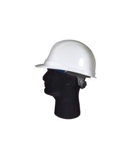
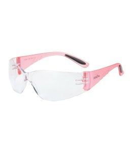
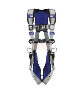
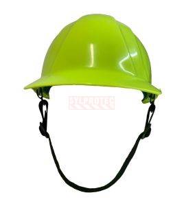
Picture the ironworker laying steel decking at the edge of a slab, tied to the Rebel line at foot level. This worker wears a harness (FPH140201XCALP) ExoFit X200 Class ALP with a stand-up dorsal D-ring, ultra-thin TenActiv cut resistant gloves (GS21TXUGFN), eyewear (YAZ2600) with a clear polycarbonate lens against chips, and an Omega II type 2 class E helmet (TA14OR), held by its Delta Plus chinstrap (TA14CS). A fluorescent orange class 2 vest (VV50) keeps the worker visible to the crane operator.
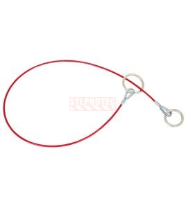
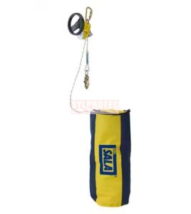
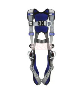
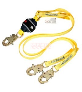
The teammate who alternates between the edge and supported work wears an ExoFit (FPH140201XCAP) X200 Class AP harness with positioning D-rings. Anchor around a beam, at edge height or higher, with a PeakWorks galvanized cable sling (FPAECG). For access, a twin-leg Y lanyard (FPL124657XX) maintains 100% tie-off, never on the Rebel line. The second worker has a separate retractable (FPLR3503822) Smart Lock 30 ft leading edge lifeline. Plan rescue with the Rollgliss (FPLR550) R550 with built-in hoist, then mark the area with red DANGER barricade (ECT3RE9) tape and black non-slip warning tape (ECT748).

Data sheet
You might also like
The PROTECTA Rebel 3590544 self-retracting lifeline is certified to CSA Z259.2.2-17 for leading edges (SRD-LE). Its corrosion resistant 7/32 in (5.56 mm) galvanized steel wire rope is 33 ft (10 m) long and provides a 30.1 ft (9.2 m) working length. The external polyester energy absorber with fall indicator limits forces when the cable is loaded over an edge. Red thermoplastic housing, carrying handle, swivel eye and anchorage carabiner included. Capacity of 130 to 310 lb (59 to 140 kg), including clothing and tools.
This item is not stocked. Allow 12 days for delivery.